Index Testing
The Stormwater Laboratory is equipped with all of the necessary equipment to perform several ASTM tests on materials and soils. Some of the capabilities are listed below with pictures of the required equipment.
- ASTM D4632-91 (2008) Standard Test Method for Grab Breaking Load and Elongation of Geotextiles. This test is applied to determine the effective strength of the fabric, that is, the strength of the material in a specific width with the additional strength contributed by adjacent material (ASTM Standard D4632 2008). The equipment used to perform this test is shown in Figure 1 below.
- ASTM D5035-06 Standard Test Method for Breaking Force and Elongation of Textile Fabrics (Strip Method). This test method is applicable to both ravel strip and cut strip procedures. The ravel strip procedure is for determining the force required to break a specific width of fabric, and is useful for comparison of the effective strength of yarns in the fabric with the combined strength of an equal number of the same nonwoven yarns. The cut strip procedure is applicable to dipped or coated felted fabrics and nonwoven fabrics (ASTM Standard D5035-06 2008). The equipment used to perform this test is shown in Figure 1 below.
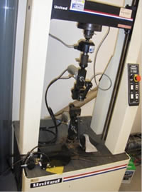
Figure 1 : Apparatus for grab breaking load and elongation of geotextiles (tensile testing machine with quick release adapter and clamps) – ASTM D4632 and D5035
- ASTM D4833-07 Standard Test Method for Index Puncture Resistance of Geomembranes and Related Products. This test method is intended to establish an index value by providing standard criteria and as a basis for uniform reporting, (ASTM Standard D4833 2007). The equipment used to perform this test is shown in Figure 2 below.
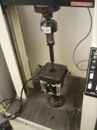
Figure 2 : Apparatus for puncture test (Tensile/compression testing machine, clamp attachment and solid steel rod) – ASTM D4833
- ASTM D4491-99a (2009) Standard Test Methods for Water Permeability of Geotextiles by Permittivity. This index test evaluates the volume of water that would pass through a geotextile under a given head of 50 mm (2 inches) over a particular cross-sectional area. Permittivity is an indicator of the quantity of water that can pass through a geotextile in an isolated condition (ASTM Standard D4491-99a 2009). The equipment used to perform this test is shown in Figure 3 below.
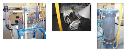
Figure 3 : Apparatus for geotextile permittivity test (permittivity system, de-airing device and vacuum pump) – ASTM D4491
- ASTM D4751-04 Standard Test Method for Determining Apparent Opening Size of a Geotextile. This index determines the apparent opening size (AOS) of a geotextile by sieving glass beads through a geotextile. The test method reflects the approximate largest opening dimension available for soil to pass through, (ASTM Standard D4751 2004). The equipment used to perform this test is shown in Figure 4 below.
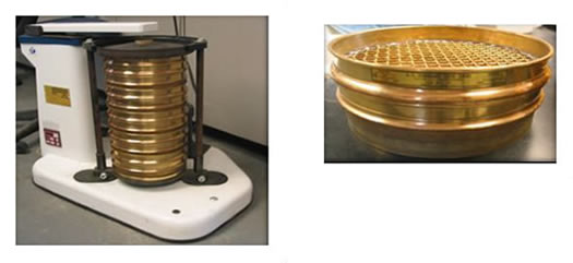
Figure 4 : Apparatus for apparent opening size test on geotextiles (rotary sieve shaker and sieve set) – ASTM D4751
- ASTM D1556-07 Standard Test Method for Density and Unit Weight of Soil in Place by the Sand-Cone Method. This test method is for determining the in-place density and unit weight of soils using a sand cone apparatus, and is applicable for soils without appreciable amounts of rock or coarse materials in excess of 1 ½ inches (38 mm) diameter (ASTM Standard D1556 2007). The equipment used to perform this test is shown in Figure 5 below.
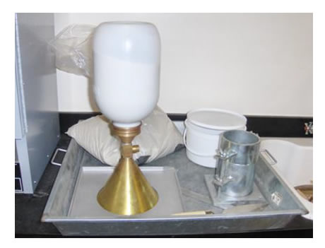
Figure 5 : Apparatus for determining density/unit weight by sand cone method – ASTM D1556
- ASTM D6938-08a Standard Test Method for In-Place Density and Water Content of Soil and Soil-Aggregate by Nuclear Methods (Shallow Depth). This test method is a rapid, nondestructive technique for in-place measurements of wet density and water content of soil and soil-aggregates and the determination of dry density (ASTM Standard D6938 2008). The equipment used to perform this test is shown in Figure 6 below.
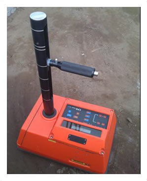
Figure 6 : Apparatus for determining field moisture and density/unit weight by nuclear density gauge – ASTM D6938
- ASTM D2434-68 (2006) Standard Test Method for Permeability of Granular Soils (Constant Head). This test method is for determining the coefficient of permeability under a constant-head and for laminar flow of water through granular soils (ASTM Standard D2434-68 2006). The equipment used to perform this test is shown in Figure 7 below.
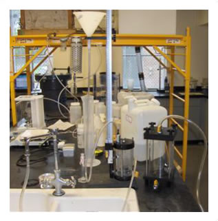
Figure 7 : Apparatus for determining hydraulic conductivity of soils – ASTM D2434
- ASTM D2216-05 Standard Test Methods for Laboratory Determination of Water (Moisture) Content of Soil and Rock by Mass. This test method is the laboratory determination of the water (moisture) content of soil, rock and similar materials where the reduction in mass by drying is due to loss of water (ASTM Standard D2216 2005). The equipment used to perform this test is shown in Figure 8 below.
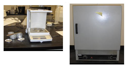
Figure 8: Apparatus for determining moisture content of soil – ASTM D2216 and D1140
- AASHTO T88-00 (2004) Standard Method of Test for Particle Size Analysis of Soils. This test method is for the quantitative determination of the distribution of particle sizes of soils (AASHTO T 88 2004). The SMART laboratory is equipped to perform test only on particles retained on 75-μm (No. 200) sieve; however, access to equipment required for particles finer than 75-μm are available at the UCF geotechnical laboratory. The equipment used to perform this test is shown in Figure 9 below.
- ASTM D1140-00 (2006) Standard Test Methods for Amount of Materials in Soils Finer than No. 200 (75-μm) Sieve. This test method is used to determine the amount of material finer than a 75-μm (No. 200) sieve by washing. Particles finer than 75-μm (No. 200) sieve are more efficiently and completely separated from larger particles by wet sieving than with dry sieving. For accurate determination of the percent finer than 75-μm this test method is recommended prior to dry sieving (ASTM Standard D1140-00 2006). This test method is an integral part of AASHTO T88. The equipment used to perform this test is shown in Figure 9 below.
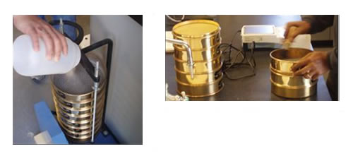
Figure 9 : Apparatus for determining soil grain size analysis – ASTM D422
- AASHTO T99-97; (ASTM D698-07e1) Standard Test Methods for Moisture-Density Relations of Soils Using 2.5-kg (5.5-lb) Rammer and a 305-mm (12-in) Drop. This test method describes laboratory compaction methods used to determine the relationship between molding water content and dry unit weight of soils (compaction curve) compacted in a 4 or 6 inch diameter mold with a 5.50-lb rammer dropped from a height of 12 inches producing a compactive effort of 12400 ft-lb/ft3 (ASTM Standard D698 2007, AASHTO T 99-97 2001). The equipment used to perform this test is shown in Figure 10 below.

Figure 10 : Apparatus used in compaction test – ASTM D698
- ASTM D854-00; AASHTO T100-06 Standard Method of Test for Specific Gravity of Soils. This test method determines the specific gravity of soil solids passing a sieve by means of a water pycnometer (ASTM Standard D854 2006, AASHTO T 100-06 2006). The equipment used to perform this test is shown in Figure 11 below.
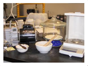
Figure 11: Apparatus for determining specific gravity of soil – ASTM D854
- ASTM D4318-05; AASHTO T89-02; and AASHTO T90-00 (2004) Standard Test Methods for Liquid Limit, Plastic Limit and Plasticity Index of Soils. This test method is used to characterize the fine-grained fractions of soils and to specify the fine-grained fraction of construction materials. In addition, it is used with other soil properties to correlate with engineering behavior such as compressibility, hydraulic conductivity, compactability, shrink-swell and shear strength (ASTM Standard D4318 2005, AASHTO T 89-02 2004, AASHTO T 90 2004). The equipment used to perform this test is shown in Figure 12 below.
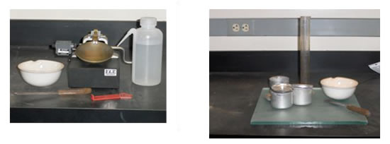
Figure 12: Apparatus for determining liquid limit and plastic limit of soil – ASTM D4318
Hydraulically Adjustable Test Beds
The Stormwater Management Academy Laboratory is equipped with two 12 inch deep 30 foot by 8 foot hydraulically adjustable test beds. These test beds are calibrated for the following slopes; 5:1, 4:1, 3:1, 2:1 with intermediary slopes also achievable. Each test bed is drained via 270 evenly spaced ¼ inch diameter holes in the bottom of each test bed. Each hole is fitted with a barbed nipple fitting with polyethylene tubing, see Figure 13 below. The tubing can either drain freely into collection bins for measurement – either water quality, water quantity, or both – or it can be connected to a pipe reservoir used to control the water table level in the test bed, see Figure 14 below. The downstream end of each test bed is fitted with two triangular surface flow collection spillways, see Figure 15 below. This unique setup allows for testing ranging from erosion control applications to runoff coefficient/curve number verification to water quality and quantity testing from simulated water sheds just to name a few.
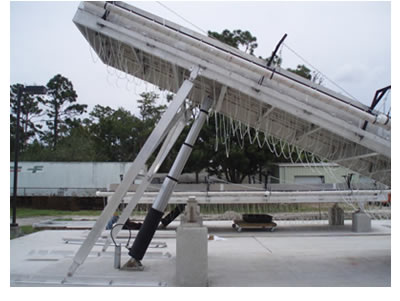
Figure 13: Hydraulically Lifted Test Bed
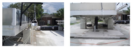
Figure 14: Pipe Reservoir System for Test Beds
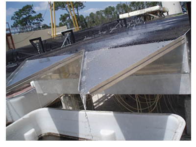
Figure 15: Surface Flow Collection Spillways
Rainfall Simulator Capabilities
A rainfall simulator is used with the test beds to simulate rainfall and subsequent runoff conditions, see Figure 16 below. The rainfall simulator is designed and operated over a range of rainfall intensities common for Florida; however other rainfall intensities are also achievable. The UCF rainfall simulator is capable of rainfall intensities ranging from 0.25 inches per hour to 12 inches per hour. The drop size and velocity from the rainfall simulator is important for mimicking erosion patterns observed in the field and must be consistent with natural rainfall. The UCF rainfall simulator shown in Figure 16 is composed of a pressurized distribution system with specialized water spray nozzles. The rainfall simulator must be maintained at a height no less than seven feet above the test bed to achieve the desired velocity. The nozzles are designed to produce a drop size that would be similar to natural rainfall. The drop size was measured using a Joss-Waldvogel Disdrometer. A drop size distribution curve is measured for natural rain and compared to that from the rainfall simulator, see Figure 17 . The drop size produced by the rainfall simulator was shown to sufficiently mimic natural rain drop sizes.
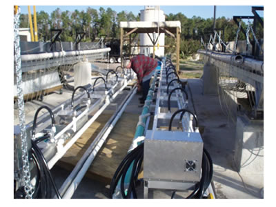
Figure 16: Stormwater Management Academy Rainfall Simulator
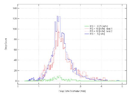
Figure 17: Drop-size Histograms for Four UCF Rainfall Simulator Simulations
Erosion Control Testing
The UCF Stormwater Management Academy has constructed a laboratory that can provide evaluation of erosion and sediment control products under typical Florida conditions using different rainfall rates and soils. The following issues related to erosion and sediment control can be addressed at this facility:
- What are the best new erosion control products and methods for Florida conditions?
- What are the performance characteristics for Florida conditions?
- What data are available for proper design and operation?
- What are the benefits and potential constraints to use/implementation?
Typical test setup for different erosion and sediment control testing using the test beds and rainfall simulator are shown in Figure 18, Figure 19, and Figure 20 below.
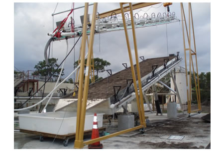
Figure 18: Typical Test Bed and Rainfall Simulator Setup for Erosion Control Testing
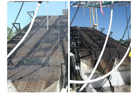
Figure 19: Erosion Testing in Action
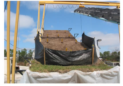
Figure 20: Typical Silt Fence Test Setup
The Stormwater Management Academy Laboratory also has Type 5 (curb) and Type C (drop) inlets available to test inlet protection devices, see Figure 21, Figure 22, and Figure 23 below. Testing capabilities include water quality analysis, flood abatement, turbidity reduction, as well as index testing of the materials.
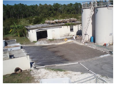
Figure 21: Type 5 (Curb) Inlet Test Site
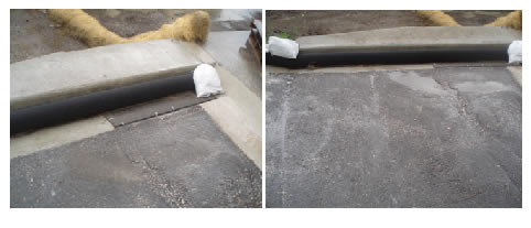
Figure 22: Type 5 (Curb) Inlet Setup
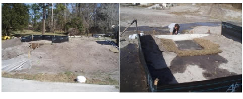
Figure 23: Type C (Drop) Inlet Test Setup
The Stormwater Management Academy Laboratory also has the cabalility to do testing with polymers for turbidity reduction. Testing includes a “lab” component which examines the effect of dose and mixing time on turbidity removal for different soil types and a “field” component which utalizes the academies field scale treatment channel, see Figure 24, Figure 25, and Figure 26 below.
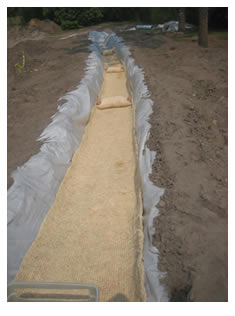
Figure 24: Polymer Treatment Channel
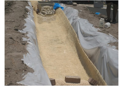
Figure 25: Polymer Treatment Channel (Upstream)
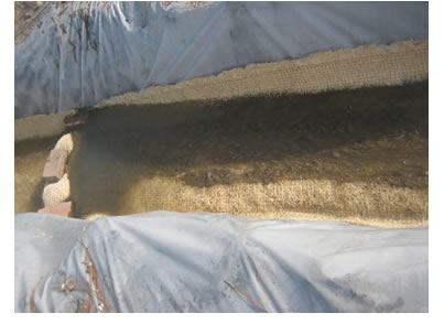
Figure 26: Polymer Treatment Channel during Test
Green Roofs
The Stormwater Management Academy is one of the leading green roof research groups in the state of Florida. The Academy has the ability to study green roofs on a “lab” scale (See Figure 27) as well as monitor full scale green roofs (See Figure 28). Examination of green roof water quality, water quantity, and plant selection are the primary focus of much of the Academy’s efforts. The Academy also examines construction techniques and materials, see Figure 29 and Figure 30 below.
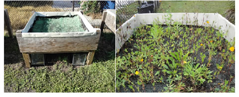
Figure 27: Green Roof Lab Scale Setup
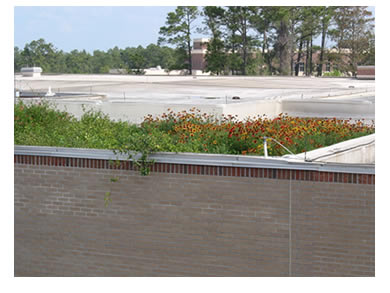
Figure 28: Full Scale Green Roof at UCF Main Campus
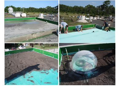
Figure 29: Stormwater Lab Green Roof Construction
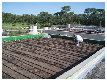
Figure 30: Stormwater Lab Green Roof Planting
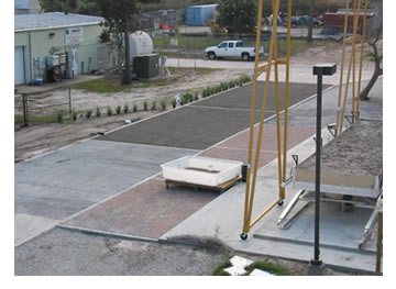
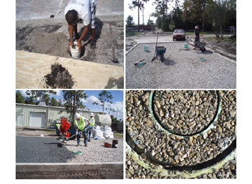
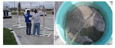
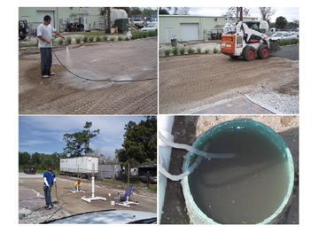
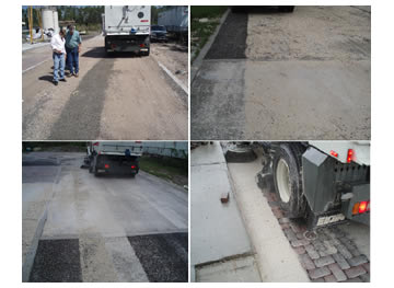
Pervious Pavements
The Stormwater Management Academy Research Laboratory has eight different types of pervious and permeable pavements installed for testing. The primary focus of the research completed thus far is to examine the infiltration rates of new, loaded, and rejuvenated pervious and permeable pavements. Figure 31 below shows a section of the pervious and permeable pavements at the Stormwater Research laboratory. Figure 32 shows the installation of the Embedded Ring Infiltration Kit (ERIK) device which allows for in-situ measurement of pervious pavements. The ERIK device was developed at the Stormwater Academy as a way to measure the performance of pervious and permeable pavements over time and under different conditions. Figure 33 shows ERIK testing being performed on newly installed pervious concrete. The ERIK test is applicable on all pervious and permeable pavement systems. Figure 34 shows the pavements getting loaded and subsequent ERIK testing. All the pervious and permeable pavements underwent extreme loading to simulate long term sediment accumulation as well as sediment transport into the system via watering in (rain) and compaction (vehicle traffic). Finally, Figure 35 shows rejuvenation of the pavement sections using a vacuum truck. Additional testing capabilities include strength testing, porosity testing, and water quality testing.